| Column Schedule Options
|
- Schedule
Title - The text field is used to enter the column schedule title.
- Max
Elevation Row - When on, a row is added to the schedule at the
maximum elevation of the model even if it does not contain concrete columns.
That is, the highest floor definition in the model. When off, the highest
elevation (floor definition) containing concrete columns is used.
- Column
Marks - When on, a row is added to the schedule table for the
column marks. When off, no row is added and the
Column Mark Prefix option is disabled.
The column marks generated during the creation of the column schedule are
written to the underlying linear members in the Structural model by defining
the Structural Data attribute
Mark (if undefined previously).
-
Column Mark Prefix - Used to generate
prefaced column marks. Column marks begin with the entered prefix and are
coupled to sequence numbers (C1, C2, C3).
-
Recalculate Column Marks - When on,
column marks are recalculated whenever there is a change in the model.
|
| Location Marks
|
When selected other than
None, rows are added to the schedule
table for the location marks.
Select from one of these options:
- Column Grid
- Geographic Coordinates
- Global Coordinates
Note: For
Geolocated model, the output will have Geo Coordinates columns in the schedule
table.
If
Group Similar Columns is enabled, all the
location marks for a given column configuration are listed in the table column.
If
Group Similar Columns is disabled, one
location mark is generated for each configuration.
-
Dimensions - When on, dimensions are
automatically generated on column ends that do not align with set story
elevations. When off, no dimensions are generated, and the Dimensions settings
are disabled.
-
Floor Elevation Labels - Determines the
position of floor elevation labels on the schedule.
Select from one of these options:
- Output to
External File - When on, enables sending schedule to external file,
rather than confining the entire region of schedule data to master file. The
variable
MS_DRAWINGDIR determines the output location
for external graphical schedule. During process of creating
schedules, you will get an interface allowing you to select or create a new
external file in which the Graphical Column Schedule be created.
Note: In the process of external output file creation and
opening it is a silent check in and check out process.
|
| Column Schedule Filters
|
-
Group Similar Columns - When on,
repetitive column configurations are grouped into a single table column. When
off, each column configuration is listed in a separate table column.
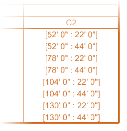
Column
configuration occurring in eight locations
- Show
Off-Grid Columns - When on, columns that are located off the grid
system, are included in the schedule. They are displayed without grid location
labels. When off, off-grid columns are excluded from the schedule.
- Show
Lateral Columns - When on, columns of the structural class
Lateral are included in the schedule.
Tip: Typically, this setting is off
and only columns of the structural class
Gravity are included.
- Show
Sloped Columns - When on, sloped columns are resymbolized in the
schedule. When off, sloped columns are excluded from the schedule.
- Sloped
Label - Specifies a text label drawn in place of sloped columns.
The note is generated at the beginning of each sloped column segment, and is
oriented vertically in the column schedule table.
|
| Concrete Symbols & Seeds
|
Used to select the graphic cells used for
representing four types of reinforcement splices occurring between columns at
story intersections. Clicking on each cell setting opens a Cell Library drop
down list to select the cell applied for each splice.
The cells used in the schedule table correspond to
the different types of reinforcement splices existing in the Structural model.
These reinforcement splices are defined by the ISM property
End Hook.

Reinforcement ISM
properties
- Drawing
Seed - Selects the drawing seed used to create the steel column
schedule.
-
Lap Splice - Used to select the cell
used to represent lap splices (ISM
End Hook property value set to
LapSplice).
-
Offset Lap Splice - Used to select the
cell used to represent offset lap splices (ISM
End Hook property value set to
OffsetLapSplice).
-
Mechanical Splice - Used to select the
cell used to represent mechanical splices (ISM
End Hook property value set to
MechanicalSplice).
-
Welded Splice - Used to select the cell
used to represent welded splices (ISM
End Hook property value set to
WeldedSplice).
-
Reinforcement Bar - Used to select or
browse cells to be used as the reinforcement bar.
-
90 Degree Hook - Used to select or
browse cells to be used to represent a 90 degree end hook (ISM Hook90).
- 135
Degree Hook - Used to select or browse cells to be used to
represent a 135 degree end hook (ISM Hook135).
- 180
Degree Hook - Used to select or browse cells to be used to
represent a 180 degree end hook (ISM Hook180).
-
Anchor - Used to select or browse cells
to be used to represent an anchor end hook (ISM Anchor).
|
| Section Legend
|
Used to control the layout of the
Section Legend portion of the column
schedule tables. The section legend graphically represents the unique
transverse sections that exist in the Structural model. A
transverse section represents a combination of a column section (e.g. 18x20)
and a pattern of parallel and transverse steel reinforcement bars. The
transverse reinforcement bars are annotated with callouts on the schedule
table, and are easily identified by their Bar Marks.
-
Legend Title — Sets the title that is
placed above the section legend. The text style, color, etc. of the legend
title is controlled by the same dataset part and text style as the primary
schedule title: Schedule Layout (Schedule Title) and half the size of the
primary title.
-
Bar Mark Prefix — Generates bar marks to
each column in the schedule with the set prefix. Bar marks are incremental in a
sequence number (T1,
T2, ..). The bar mark (e.g.
T1) represents the type of
reinforcement present in the column. Each bar mark in the schedule is also
shown in the Section Legend with a graphical representation of the column
section and the reinforcement.
-
Sections Per Row — Sets the maximum
number of sections that appear in a table row. Section legend having more
sections than maximum number set, are be wrapped in a new row on the next line
in the legend.
|

